Filter
Please note:

Minimum order amount: 500 UAH
Quantity of SMD: multiples 100 pcs
Buy system-on-a-chip and SOC in Ukraine
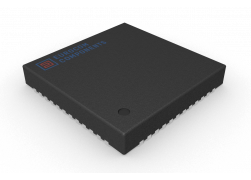
A single chip or system on a chip (SoC) is an integrated circuit that integrates a computer or other electronic system into a single chip. The single-chip system can handle digital signals, analog signals, mixed signals, and even higher frequency signals. Monolithic systems are often used in embedded systems. The scale of integration of a monolithic system is very large and usually reaches from several million to tens of millions.
Although a microcontroller typically has less than 100KB of RAM, it is actually also the structure of a small computer, a simple single-chip system with weakened functions, and the commonly accepted term "single-chip system" often used for more powerful processors that can run certain versions of Windows and Linux. The stronger function of a monolithic system requires an external memory chip, for example, some monolithic systems are equipped with flash memory. Monolithic systems can often add additional external devices. The monolithic system places increased demands on the scale of integration of semiconductor devices. To better perform more complex tasks, some monolithic systems use multiple processor cores.
Microcontroller-based single-chip system
A typical monolithic system consists of the following parts:
- At least one microcontroller or microprocessor, digital signal processor, but there can also be multiple central control cores
- The memory can be in different blocks: read-only memory, RAM, EEPROM and flash memory.
- Oscillator and phase-locked loop to provide time pulse signal.
- External equipment consisting of counters, timers and power circuits.
- Various standard connection interfaces such as universal serial bus, FireWire, Ethernet, universal asynchronous transceiver, serial peripheral, etc
- Analog to digital converter and digital to analog converter for converting digital signal to analog signal.
Voltage shaping circuit and voltage regulator
The data flow is mainly dependent on the I / O bus in the system, such as the enhanced microcontroller bus architecture of Amou International Technology Corporation. Using a DMA controller, external data can be directly transferred to memory without going through the CPU, which can greatly improve data processing efficiency.Estimated flow
Schematic diagram of the design process of a monolithic system
A complete monolithic system consists of two parts: hardware and software. The software is used to control the controller, microprocessor, or digital signal processor core of the hardware, as well as peripherals and interfaces. The design process of a monolithic system is mainly concerned with the design of its hardware and software.
As the integration of monolithic systems has reached millions of inputs, engineers must embed reusable ideas as much as possible. Most monolithic systems use predefined intellectual property semiconductor cores (IP cores, including software cores, hard cores, and hard cores) to complete rapid, reusable design. Compared to the previous IC design, the reusable design requires more standardization from the designer, such as a standardized coding style, etc.
Developers need to pay attention to the implementation of hardware drivers to achieve specific functionality. The protocol stack is an important concept associated with industry standards such as universal serial bus interfaces.
Designers typically use CAD tools to plug in kernels that have been designed (or purchased). Currently, the IDE can be used to integrate modules containing various sub-functions.
Before the engineered chip is sent to the factory for hardware production, the designer uses various methods to test the logic function of the chip. Functional verification is just as important as the design of an integrated circuit. For modern VLSI, this stage takes a lot of time and money throughout the entire design cycle.
To cope with the extremely high degree of complexity of the chip, hardware inspection languages such as SystemVerilog, SystemC, e validation languages, and OpenVera have gradually become popular. During the validation phase, system software bugs can be returned to the developer for targeted fixes.
Engineers typically use a well-designed simulator or run a program on a field programmable gate array (FPGA) to test the previous system level, behavior level (or use another term, "register transfer level" or RTL). This step is to validate the functionality of the software and hardware and the performance of the design project prior to final production of the equipment (casting), and to correct any errors in function, time and power consumption.
Among these, a working method of using arrays of programmable logic gates to prototype products allows engineers to evaluate and test the operating state of a system when various stimuli are applied to the system. Associated electronic design automation tools include Certus, which can be used to analyze and detect register transfer layer code in a system design, and to track changes in variables and signals throughout an operation.
After completing the functional validation process, engineers will also use CAD to complete the layout and routing process. At this point, they need to pay attention to which layout method can minimize signal interference and latency between connections.
